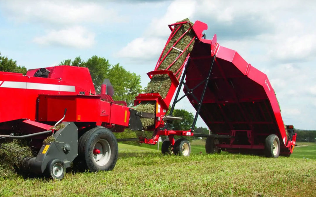
The innovative design of the hay accumulators allows it to be fully automatic without the use of hydraulics or electronics.
All you need to do to setup the baler is ensure correct hitch-pin position (centered, 8” behind bale chamber) and loosen the pressure in the bale chamber to compensate for the back pressure caused by pushing the bales up the chute. There is no extra pressure applied to the plunger and the twisting action of the chute does not deform the bales. Once your baler is set up to the accumulator by using the proper distance you are ready to start baling. The operator will bale as normal with the hay accumulator in tow behind the small square baler. The hay accumulator works by using excess energy from the baler plunger to push the small square bales to the top of the front chute. Then as gravity moves the bales downward, the last bale in each row swings a door to open the next row. As each row fills with the selected amount of hay, a series of levelers or gates are tripped to open the next row for hay. Then the last bale in the grab opens the back gate and sets the group of hay onto the field. As the hay accumulator unloads itself, springs return all of the gates back to their starting position, ready for another grab in good time before the next bale comes. There is zero user intervention required.
The bales are set on the ground, arranged to be picked up with a grapple mounted on a loader.
The Norden Tie-Grabber is designed to not only pick up a whole bundle of hay but then ties it together using Rasspe knotter from Germany. One operator is able to pick up as many as 18 bales at once. This also secures the bales together when setting them onto a wagon, trailer or truck bed.
How the Tie-Grabber Works
The primary hydraulic circuit operates the bale squeeze and the bale hooks. When activated, the squeeze bar pulls the bales in. A sequence valve then automatically activates the bale hooks. The secondary hydraulic circuit operates the twine arm and the knotter. The twine arm starts on the right hand side, and when it completes its rotation, a valve automatically diverts the flow to the knotter.
In Detail:
With the squeeze arm out and the twine arm on the right-hand side, the operator will align the left side of the Tie-Grabber with the left side of the group of bales on the ground and push the group forward to compact the group. The angle of the squeeze arm will pull the bales in as it moves forward. When the bales are compacted length wise, the operator will activate the primary hydraulic circuit. This will pull the squeeze arm in, compacting the bales sideways. The bale hooks will automatically begin to set, so the operator needs to make sure the Tie-Grabber is firmly set on the group so the hooks can set properly. With the bales properly secured, the operator can safely lift and move the group.
While traveling with the loaded Tie-Grabber, the operator will activate the secondary hydraulic circuit. The twine arm then rotates to the left side for the twine to be tied securely with the Rasspe knotter. When that is finished, the hay is ready to be deposited. When traveling to the next group the operator can return the twine arm to the right hand side.
This twine tied around the bundle of bales keeps the hay secure while traveling down the road or field and makes the stack in the barn very stable and safe. It is also possible to build a stack of bales on a pallet and move them with a forklift. Finally, some of our users will build a stack of tied bales and move them with a bale squeeze.
The Standard Grabber has the same functions of the tie-grabber but without the tying mechanism. These are convenient for unloading a bundle of hay from your wagon and into your barn.

1
Bale #1 and Bale #2 enter the Hay Accumulator and slide down the first lane on the left and into position.

2
Bale #3 enters the Hay Accumulator and slides downward and into position, rotating the gate via the actuating spring and shifting gate #1 to open lane #2.

3
Bale #4 and Bale #5 enter the Hay Accumulator and slide downward and into position.

4
Bale #6 enters the Hay Accumulator and slides downward and into position, rotating the gate switch and shifting gate #2 to open lane #3.

5
Bale #7 and Bale #8 enter the Hay Accumulator and slide downward and into position.

6
Bale #9 enters the Hay Accumulator and slides downward and into position, rotating the gate switch and shifting gate #3 to open lane #4

7
Bale #10 and Bale #11 enter the Hay Accumulator and slide downward and into position.

8
Bale #12 enters the Hay Accumulator and slides downward and into position, rotating the gate actuating spring and shifting gate #4 to open lane #5.

9
Bale #13 enters the Hay Accumulator and slides downward and into position.

10
Bale #14 enters the Hay Accumulator and slides downward and into position, rotating the back gate trip slider to engage the trip switch.

11
Bale #15 enters the Hay Accumulator and slides downward, depressing the back gate trip flipper to open the back gate.
12
Once the back gate is open, the bales push the back gate open and slide to the ground. When all bales are clear, the back gate returns to its original position and latches. All gates return to their original position.
